How to Approach MATLAB Simulink Assignments using Control Design and Simulation

MATLAB and Simulink are powerful tools widely used in engineering assignments, especially for tasks involving control systems and simulations. Whether you're tackling an assignment that involves PID control, wind turbine simulations, or general control system design, understanding the fundamental steps can make the process much more manageable. In this blog, we'll explore the key concepts and steps that can help you solve your Simulink assignment, guiding you through the process with practical advice that applies to a variety of control system assignments.
1. Understanding the Assignment Requirements

Before diving into coding and simulation work, it's essential to fully understand the requirements of your assignment. Each task will typically have specific guidelines on what you need to achieve. Common elements that may appear in these types of assignments include:
- System Modeling: You’ll be tasked with modeling systems like motors or turbines, either using transfer functions, differential equations, or state-space models.
- Controller Design: Often, you need to design and test controllers like PID or Lead controllers. This requires tuning the controllers to meet performance criteria such as settling time, overshoot, or steady-state error.
- Simulation and Validation: The assignment may require you to create Simulink models or MATLAB code to simulate your system’s behavior and validate the design of your controller.
- Report Writing: A significant part of these assignments is the report, where you must explain your approach, show the results, and justify your decisions.
The first step is to break down the assignment into clear sections based on the instructions. For instance, if your task involves both PID controller design and simulation of a wind turbine, divide it into manageable tasks such as modeling the plant, designing controllers, simulating the system, and analyzing the results.
2. Building the Open-Loop System
The foundation of any control design is understanding the system you're working with. In control systems, this is typically referred to as the "plant."
Modeling the Plant
You’ll often be given a transfer function or a set of differential equations to model the plant. For example, if the system is a DC motor, the differential equation might describe the motor’s dynamic behavior. This equation can usually be transformed into a transfer function using MATLAB’s tf() function.
For example, let’s consider a first-order transfer function for a DC motor:
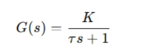
where K is the motor gain, and τ is the time constant.
In MATLAB, you can create this transfer function as:
K = 1; % Motor gain
tau = 0.5; % Time constant
sys = tf(K, [tau 1]);
Once you have the transfer function, use the step() function to analyze the system’s open-loop step response. The step response will give you insights into the system’s characteristics, such as rise time, settling time, and overshoot, which are essential for controller design.
Creating the Simulink Model
Simulink is a visual tool that lets you model dynamic systems. For open-loop systems, you can use blocks like the "Transfer Function" block to represent the plant. After creating the system in Simulink, simulate its behavior with a step input. This simulation will provide graphs showing how the system behaves over time.
For example, if you're modeling a DC motor, you can represent the transfer function using the “Transfer Function” block in Simulink. Connect it to a “Step” input block and a “Scope” block to visualize the response.
3. Controller Design and Tuning
Once the open-loop system is modeled and simulated, the next step is to design a controller. The most common controllers used in control systems are:
- Proportional (P) Controller: This controller applies a correction proportional to the error. It’s simple but may not eliminate steady-state error.
- Proportional-Integral (PI) Controller: PI controllers add an integral action that helps eliminate steady-state error, which is essential for systems that require zero error in steady-state conditions.
- Proportional-Integral-Derivative (PID) Controller: The PID controller combines all three actions: proportional, integral, and derivative. It’s widely used for its ability to quickly stabilize systems and reduce error.
PID Control in Simulink
To implement a PID controller in Simulink, use the “PID Controller” block. Connect the controller in a negative feedback loop with your plant model.
Once the controller is in place, tune it to meet the desired performance criteria. In Simulink, you can use the PID Tuner app for automatic tuning, or manually adjust the proportional, integral, and derivative gains to achieve the desired system response.
System Response and Controller Comparison
For each controller type (P, PI, PID), simulate the system’s response to a step input. Plot the system’s output and analyze its performance. Key performance indicators include:
- Settling time: The time it takes for the system to settle within a certain percentage of the final value.
- Overshoot: How much the system exceeds the desired setpoint before settling.
- Steady-state error: The difference between the desired and actual output once the system has settled.
Compare the responses of the controllers. Typically, a PID controller provides the best performance in terms of reducing overshoot and achieving faster response time, while PI or P controllers may have trade-offs such as larger steady-state errors or slower response times.
4. Advanced Control Design with MATLAB Control System Designer
In some assignments, you may be required to design more advanced controllers, such as a Lead compensator, using MATLAB's Control System Designer tool.
A Lead compensator can improve the phase margin and speed up the system response without compromising stability. The MATLAB Control System Designer allows you to design and tune controllers interactively.
Using Control System Designer
To start, use the controlSystemDesigner() function in MATLAB. You’ll be able to modify the plant and compensator in real time. You can add poles and zeros to the system, aiming to achieve specific performance goals like a desired transient response (settling time, overshoot, etc.).
As part of the assignment, you’ll need to justify the controller design choices. For example, if you're designing a Lead controller to meet a specific damping ratio and settling time, explain how the compensator's poles and zeros were selected to achieve those goals.
Take annotated screenshots of the interactions with the Control System Designer tool. These screenshots will help demonstrate the steps you took to design and fine-tune the controller.
5. Modeling and Simulating Complex Systems (e.g., Wind Turbine Control)
More complex assignments may require you to model systems with multiple interacting components, such as a wind turbine. Wind turbine control typically involves managing both the yaw angle (to face the wind) and the blade pitch (to adjust for varying wind speeds).
Modeling the Wind Turbine
To simulate a wind turbine in Simulink, you need to model both the mechanical components (the DC motors for pitch and yaw control) and the control system.
The wind turbine's yaw and pitch systems are typically controlled by brushless DC motors, which can be modeled using first-order differential equations or transfer functions. The control system will adjust the pitch and yaw angles based on wind speed and direction.
For example, the motor’s dynamic response can be approximated by a transfer function like this:
where K is the motor gain, and τ is the time constant.
Building the Simulink Model
Use blocks such as the "DC Motor" block for each subsystem (yaw and pitch). Then, connect the motors to PID controllers. The goal is to tune the controllers to achieve the desired response, which involves adjusting the motor’s rotation angle (yaw) and blade pitch.
For a realistic simulation, use varying inputs such as wind direction and speed. This will help you observe how the system responds under different environmental conditions.
6. Testing the System and Analyzing Results
Once the system is modeled and the controllers are tuned, it's essential to validate the system by testing it under different conditions.
Simulating the System with Step Inputs
Begin by applying step inputs (e.g., sudden changes in wind speed or direction) to test the system’s ability to reach the desired setpoints. This is a simple way to check if the controllers are working correctly.
Testing with Realistic Inputs
Next, simulate the system with more realistic inputs. These could be sinusoidal waveforms representing changes in wind direction or speed, or random variations to simulate real-world conditions. Observe how the system responds and adjust the PID parameters if necessary.
Documenting and Reflecting on the System's Performance
In your report, include graphs showing how the system reacts to various inputs. Reflect on the performance, including the following:
- Was the controller able to achieve the desired setpoints?
- Did the system meet performance criteria such as fast settling time or minimal overshoot?
- What limitations were present in your model, and how could you improve it?
7. Writing the Final Report
Your final report should clearly present your findings and provide detailed explanations of your approach. Key elements of the report include:
- Introduction: Outline the task and the system being modeled.
- Methodology: Describe how you approached the modeling, controller design, and simulation steps.
- Results: Present graphs, simulation outputs, and any relevant data.
- Analysis: Discuss the performance of the system and controllers, highlight any issues, and suggest improvements.
- Conclusion: Summarize the key points and outcomes.
Conclusion
MATLAB and Simulink assignments, particularly those involving control systems and simulation modeling, require a structured approach to solve. By understanding the system you're working with, designing appropriate controllers, and testing your designs under realistic conditions, you can confidently solve your matlab assignment. Always remember to provide clear explanations, justify your design choices, and critically analyze your results.